Lecture Room Setup 2.0
In 2025, we finally updated our lecture room sets (aka. “cases”) to a new concept. See Case 2.0 for motivation and design decisions.
Each room setup now consist of two TRANSflex road cases with rack modules for key components.  Both road cases fit on a euro pallet when tipped on their short side. So during transport each lecture room will occupy 120×80 cm (height approx. 140 cm) and during operation 2x 120x60cm are needed (height approx. 80cm).
Usage
TODO: Revise signal diagram and add buildup instructions: 
Case A
Contains the modules as well as the camera, mixer laptop, microphones and TODO. TODO: Picture
Case B
 Contains accessories like:
- tripod
- cable mats
- etc.
Assembly
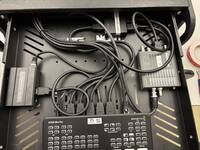
FOH Module


Custom builds:
- 2x 0.75m cable 6.3mm Jack (stereo) → angled XLR (m): For Audio De-Embedder
- 6x 0.5m cable 6.3mm Jack (stereo) → d-norm XLR (m): For additional CQ18-T outputs
Steps:
- Put cage nuts in rack rails:
- 4U on the back
- 4U on the front
- 3U on the top at (from the back side) + 2 nuts per side for CQ-18T rack mount
- Mount PoE-Switch and SDI Audio De-Embedder on short rack shelf
- Modify d-norm rack panel to fit TRUE1 connector (add additional hole)
- Connect power distribution panel to TRUE1 connector (solder or crimp connectors)
- Place remaining items on back and front
- Connect ethernet and SDI cables
- Connect 6.3mm jack cables to audio outputs 1 and 2 of the SDI Audio De-Embedder
- Connect 1m XLR (f) to angled XLR (m) cables to the 4 audio outputs of the wireless receiver
- Place audio mixer on the top, connect 4 microphone and 2 SDI channels to inputs 1-6
- Connect 6.3mm jacks (from the d-norm XLR outputs) to aux channels 1-6 of the audio mxier
- Screw down remaining rack panels
Items:
- TODO
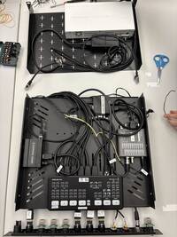
Lectern Module

Custom builds:
- Solder 2 Cinch d-norm sockets to the ends of an 1.5m 3.5mm jack → 2x Cinch cable (for ATEM audio input)
- TODO: Build 12V power distribution
Steps:
- Preparation:
- Put 16 cage nuts in the rack rails (2 rack units at the front and back)
- Mount ethernet switch on rack shelf (double-sided tape) leaving 1 cm to the left side
- Connect ethernet cables (to I/O panel) and dress them into a wire harness (TODO: upload picture):
- 3x 1.0m ethernet running in 1cm gap between switch and rack tray wall
- TODO: Mount power supply on rack tray and connect to ethernet switch
- Remove rack drawer from its rails and put devices on it using double-sided tape:
- Mount ATEM Mini centered on right at the front edge
- Mount Raspberry Pi on the left so that HDMI still goes past the ATEM mini
- Mount Up-Down-Cross on right side with SDI pointing to the front and bottom side up (this way the DIP switches will still be accessible)
- Place HDMI-Splitter at the back in a way that cables run fine
- Connect cables running on the sliding tray:
- 0.5m HDMI from Raspberry Pi to ATEM Mini, Input 4
- 0.5m HDMI from ATEM Mini Output to HDMI splitter
- 0.5m HDMI from HDMI splitter to Up-Down-Cross
- Connect cables running from drawer to I/O panel and dress them into a wire harness
- 3x 1.5m HDMI to ATEM inputs 1-3
- 1x 1.5m HDMI from HDMI splitter
- 1x 1.5m Ethernet from Raspberry Pi
- 1x 1.5m Ethernet from ATEM Mini
- 1x 1.0m SDI from Up-Down-Cross
- 1x 1.5m 3.5mm Jack to Cinch (d-norm, see above)
- TODO: Power (don't connect to power supply yet)
- Connect wire harness to I/O d-norm panel (but don't connect ethernet to the switch yet)
- Now you'll have two parts: The drawer connected to the I/O panel with HDMI, SDI and audio as well as the rack tray with the ethernet switch
- Assembly:
- Adjust the length of the rack drawer rails and mount them in the top rack unit
- Slide in the drawer:
- connect with the rails
- grab ethernet cables (coming from drawer) and let them hang out the back of the module
- place I/O panel in front of the rack module (don't screw down yet!)
- Slide in the rack tray with the switch:
- screw down at lower rack unit at the back of the rack module
- make sure, that the wire harness coming from the rack drawer is fully at the right side of the switch (when looking from the back of the rack module)
- connect 12V power cable from wire harness to power supply
- Connect I/O panel
- connect 220V-side of power supply to TRUE1 socket of the I/O panel
- connect the 3 ethernet cables to their respective sockets
- screw down I/O panel


